
from light aircraft or non-FMS turboprops to the Boeing 737 Next Generation (NG) cockpit presents a steep learning curve. The primary operational hurdle for transitioning pilots is mastering the Flight Management System (FMS). Serving as the central operational hub on the modern flight deck, the FMS is the primary interface for flight planning, lateral and vertical guidance navigation, and performance optimization. Developing a precise, systematic methodology for data entry and CDU manipulation is critical to managing cockpit workload during high-tempo airline operations.
Ready to fast-track your transition? Book a B737 type rating discovery call with Las Vegas Flight Academy today at 818-489-1738 to schedule your Level D simulator session.
737 Ng Fms Guide: Understanding the Core Flight Management System (FMS) Architecture
737 ng fms guide explains that the Boeing 737 NG FMS architecture is an integrated flight guidance system. It features the Flight Management Computer (FMC) as the computational core and the Control Display Unit (CDU) as the pilot interface. It processes sensor inputs from GPS, IRS, and radio navigation to deliver precise lateral (LNAV) and vertical (VNAV) flight path guidance.
successfully operate a commercial transport category jet, you must first master its integrated system architecture. The FMS on the Boeing 737 NG acts as an overarching manager that orchestrates the aircraft’s lateral and vertical trajectories. Rather than operating in isolation, the FMS aggregates data from multiple onboard sensors. Computes complex flight profiles, and sends steering commands directly to the Digital Flight Control System (DFCS) and autothrottle.
The Brain and the Pilot Interface
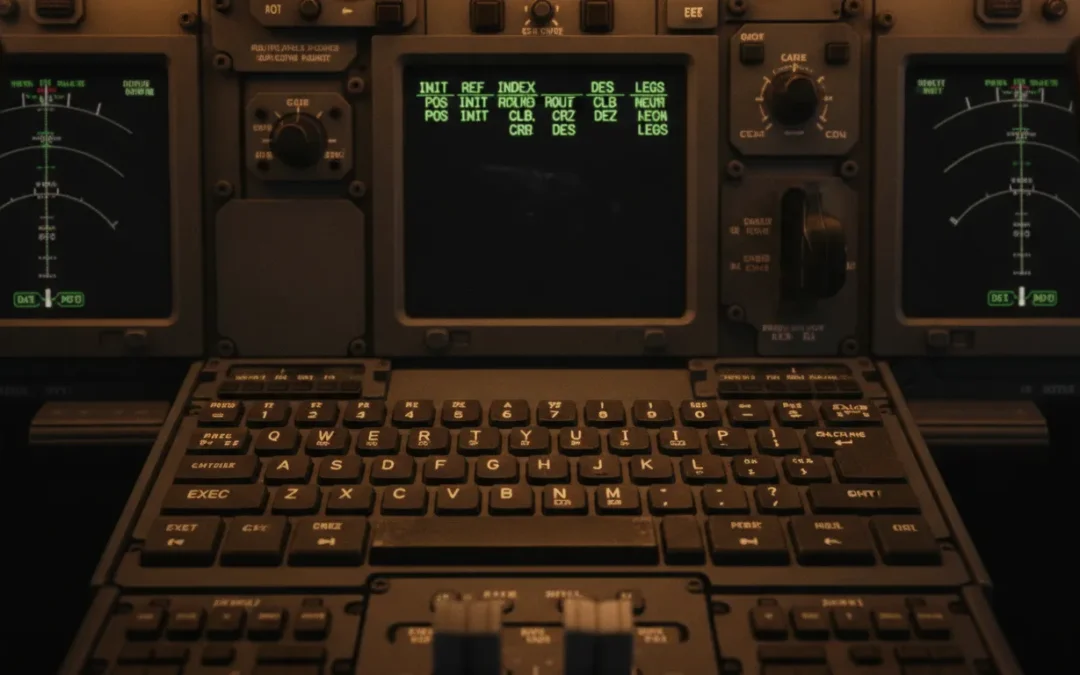
FMS is conceptually split into two primary components: the Flight Management Computer (FMC). Which serves as the physical computing unit, and the Control Display Unit (CDU), which is the pilot’s interface. The FMC performs the heavy computational lifting, calculating optimal climb gradients, fuel burn rates, cruise profiles, and descent paths. Pilots talk to this computer using the CDU, located on the center pedestal. During your type rating or recurrent training, mastering 737 NG FMS operations will become second nature as you learn to navigate CDU pages efficiently.
standard 737 NG installations, dual FMCs operate in a master-slave configuration, ensuring complete redundancy. If the primary FMC experiences an in-flight failure, the secondary computer immediately assumes control, preserving the active flight plan and guidance parameters without interruption. This cross-talk capability ensures that critical navigation and performance calculations remain available to the flight crew throughout the flight, even during complex instrument procedures in busy terminal areas.
Visual Flight Path Integration
FMS does not operate in a vacuum; it displays its calculations and navigation data on the primary flight deck displays. The Navigation Display (ND) serves as the primary visual reference for the FMS lateral path. The active route, terminal procedures, and waypoints are rendered as a solid magenta line on the ND, helping flight crews maintain superior situational awareness. Pilots must be skilled in utilizing both LNAV and VNAV modes on the Mode Control Panel (MCP) to ensure the aircraft precisely follows the FMS-guided trajectory.
, the FMS is integrated with the Primary Flight Display (PFD), feeding target speeds, flight director cues, and altitude restrictions directly into the pilot’s primary field of view. This integration ensures that the pilot can cross-verify that the automated flight guidance systems are executing the programmed flight path correctly. The synergy between the FMC, autopilot, autothrottle, and flight displays is what makes the 737 NG an incredibly stable and highly reliable platform to operate. Ensuring high-fidelity flight path control from takeoff to touchdown.
What is the Difference Between PDCS and FMC in the Boeing 737?
primary difference is that the historical Performance Data Computer System (PDCS) only calculated vertical thrust and speed profiles for fuel conservation. Whereas the modern Flight Management Computer (FMC) integrates a global navigation database to manage both lateral navigation (LNAV) and vertical navigation (VNAV) path guidance automatically.
pilots must appreciate the technological evolution of the Boeing 737 flight deck to understand why modern FMS procedures are structured the way they are. Early variants of the Boeing 737, specifically the 737-200, relied on basic analog instrumentation and independent navigation receivers. As fuel prices rose, the need for automated performance calculations led to the introduction of the Performance Data Computer System (PDCS) in 1979. Which laid the groundwork for today’s fully integrated FMCs.
Role of the Historical PDCS
PDCS was a revolutionary addition to the 737-200 cockpit, designed primarily to reduce fuel consumption. By processing engine parameters, weight, and atmospheric conditions, it computed optimal EPR (Engine Pressure Ratio) targets and target climb, cruise, and descent speeds. However, the PDCS had a critical limitation: it did not possess a navigation database. It could not steer the aircraft laterally. Flight crews still had to tune VOR and ADF stations manually and track radial courses using paper charts, using the PDCS solely as an advisory performance calculator.
The Move to the Modern FMC
introduction of the Boeing 737-300 Classic in 1984 marked the debut of the true Flight Management Computer. This system introduced a large navigation database that housed global waypoints, airways, airports, and standard terminal procedures. This allowed the computer to calculate and execute a complete lateral and vertical flight profile. In the modern 737 NG, the FMC serves as the absolute core of all navigation, autopilot, and autothrottle systems. It is the most critical system for pilots during learn advanced 737 FMS management during type rating curriculums.
System Integration Comparison
the standalone PDCS, the modern FMC is fully integrated with the Inertial Reference System (IRS), GPS receivers, and the auto-flight system. It dynamically adjusts thrust limits, tracks the active navigation database route, controls the flight director, and guides the autothrottle to maintain precise vertical and speed profiles. This high level of system integration minimizes crew workload and maximizes safety in modern, congested airspace. To illustrate the functional differences between these generations of flight deck automation, review the comparison table below.
| Feature / Capability. | PDCS (Historical – 737-200). | FMC (Modern NG – 737-800). |
|---|---|---|
| Navigation Database. | None. (Manually tuned terrestrial navaids). | Full Global Database. (Airways, SIDs, STARs, Approaches). |
| Flight Path Guidance. | Vertical / Thrust management advisor only. | Fully Automated Lateral (LNAV) and Vertical (VNAV). |
| Autopilot Integration. | No direct lateral coupling. | Direct lateral and vertical steering commands (MCP). |
| Position Updating. | Manual coordinates entry. | Continuous GPS, IRS, and DME-DME radio updating. |
| Crew Workload. | High. (Paper chart plotting and manual radio tuning). | Low. (Automated routing and automated navaid tuning). |
FMC Initialization and Reference Airport Setup (POS INIT & IRS Alignment)
the 737 FMC requires verifying database currency on the IDENT page, entering the reference airport on the POS INIT page. And aligning the Inertial Reference System (IRS) by copying the GPS coordinates into the SET IRS POSITION field to establish the aircraft’s geographic reference.
preflight sequence in the Boeing 737 NG begins with a structured initialization process on the Control Display Unit (CDU). This phase is critical because all downstream calculations, performance predictions, and lateral guidance paths depend entirely on establishing a highly accurate initial position. Mistakes made during initialization can propagate throughout the flight plan, leading to map shifts or navigation errors in flight.

Establishing the Initial Position
power-up, the pilot’s first step is to verify the navigation database validity on the IDENT page, ensuring the active cycle has not expired. Following cycle verification, the pilot accesses the POS INIT (Position Initialization) page. Entering the four-letter ICAO code for the departure airport into the REF AIRPORT field pulls up the airport’s reference coordinates. This serves as the baseline geographical reference for the aircraft’s IRS and GPS navigation systems.
Aligning the Inertial Reference System
establish precise self-contained navigation, the dual Inertial Reference Systems (IRS) must be aligned. This is accomplished by turning the IRS mode selectors on the aft overhead panel from OFF to NAV. The units begin a self-alignment process that requires the aircraft to remain completely stationary. The pilot completes alignment by copying the active GPS position coordinates from page 2 of the POS INIT page and pasting them into the SET IRS POS line on page 1. Ensuring the FMC and IRS have a highly precise starting coordinate.
Here is the standard step-by-step procedure for FMC initialization and IRS alignment:
- Verify Ident Data. Open the IDENT page and confirm that the aircraft model matches, and that the active navigation database cycle is current.
- Access Position Initialization. Press the POS INIT key on the CDU to open the initialization page.
- Enter Reference Airport. Key in your departure airport’s four-letter ICAO code (e.g., KLAS for Las Vegas) and insert it into the REF AIRPORT line.
- Set Gate Position. Enter the specific gate number if available to refine the reference coordinates for maximum accuracy.
- Align IRS Overhead. Switch both IRS knobs on the overhead panel to NAV, then copy the most accurate GPS coordinate into the scratchpad.
- Paste IRS Coordinates. Paste the copied GPS coordinates into the SET IRS POS field to complete the initialization.
this preflight sequence repeatedly is a major focus during prepare for FMS-intensive simulator sessions. In our high-fidelity Level D simulators, pilots learn to execute these checklists systematically, developing the fluid cockpit discipline and muscle memory required for line operations.
Entering the Flight Plan: Routing, SIDs, and STARs
the flight plan in the 737 FMC involves entering the departure airport and route on the RTE page, selecting terminal procedures via the DEP ARR pages. And resolving any resulting route discontinuities on the LEGS page by copying and pasting waypoints to establish a continuous lateral path.
the FMS has established its starting position, the flight crew can begin entering the active flight plan. This process defines the lateral track that the aircraft will follow once LNAV is engaged. Transitioning pilots must understand how the FMC structures routes using airways and waypoints, and how to verify that the entered data matches the cleared ATC routing.

Building the Lateral Route
routing phase begins on the Route (RTE) page. The pilot inputs the departure airport, destination airport, and company flight number on page 1. Page 2 is where the actual airway and waypoint matrix is constructed. The CDU is designed with a strict “VIA” and “TO” column structure. Airways are entered into the left-hand (VIA) column, while the corresponding terminating waypoints are entered into the right-hand (TO) column. If flying a direct segment between two points, entering “DIRECT” into the VIA column establishes the straight-line leg.
column-based data entry system requires absolute precision. Entering an incorrect airway identifier or waypoint can result in a “database error” or, worse, an incorrect route loading. Transitioning crews must cross-check every waypoint listed on the LEGS page against their computerized flight plan and terminal charts. Ensuring no critical waypoints have been omitted or misspelled before activating and executing the route.
Selecting Terminal Procedures (SIDs and STARs)
procedures link the departure runway to the enroute structure and the enroute structure to the final approach. To program these, the pilot accesses the DEP ARR (Departures and Arrivals) index page. From here, they select the active departure runway and the corresponding Standard Instrument Departure (SID) with its transition waypoint. On the arrival side, they select the Standard Terminal Arrival Route (STAR), the transition fix, and the planned instrument approach. The FMC automatically extracts the coordinate sequence and altitude/speed restrictions for these procedures from the navigation database.
Resolving Route Discontinuities
route discontinuity, indicated by box prompts on the LEGS page, represents a break in the lateral flight path. This occurs when the FMC cannot determine how to link two consecutive route segments, typically between a SID and the enroute portion, or a STAR and the approach. LNAV cannot be engaged or maintained while a discontinuity exists. To resolve it, the pilot copies the waypoint immediately following the discontinuity into the scratchpad and pastes it over the discontinuity box prompts. Subsequently pressing the EXEC key to close the gap and establish a continuous magenta line on the Navigation Display.
Performance Initialization and Navigating Cost Index
initialization on the PERF INIT page requires entering the aircraft’s zero fuel weight, fuel reserves, cruise altitude. And Cost Index (CI) to calculate the vertical flight profile, engine thrust limits, and optimal vertical navigation (VNAV) climb, cruise, and descent paths.
the lateral route defined, the next critical step is initializing the aircraft’s performance parameters. This step tells the Performance Database (PDB) inside the FMC how to compute the vertical flight profile. Vertical Navigation (VNAV) relies entirely on these inputs to calculate target speeds, thrust limits, fuel predictions, and the precise Top of Descent (T/D) point.
Inputting Weights and Cruise Altitudes
initialization is conducted on the PERF INIT page. The pilot enters the aircraft’s Gross Weight (GW) or Zero Fuel Weight (ZFW). Keying in the ZFW allows the FMC to automatically calculate the total gross weight by adding the fuel quantity sensed on board. The pilot then enters the planned fuel reserves and the Cost Index (CI) assigned by the airline dispatch. Finally, entering the cruise altitude and average cruise winds allows the computer to construct the target vertical path.
weight entry is a safety-critical requirement. If the entered weight is lower than the actual weight of the aircraft. The FMC will calculate speeds that are too slow for climb and cruise, reducing stall margins. Conversely, over-entering weight can cause the computer to target excessively high speeds and climb thrust settings, leading to inefficient operations. Double-checking these values against the final load sheet is a fundamental checklist item for all flight crews.
Ready to elevate your training? Schedule your Boeing 737 Type Rating training in our certified Level D simulator today.
The Role of Cost Index (CI)
Cost Index (CI) is a highly powerful tool used by airlines to manage operating economics. Expressed as a number from 0 to 999, it is a ratio of time cost to fuel cost:
- Cost Index of 0. Tells the FMC to minimize fuel burn. The computer will calculate the most aerodynamically efficient speed schedule, resulting in slower climbs, cruises, and descents, maximizing fuel economy.
- High Cost Index. Tells the computer that time is highly critical. The FMC will command faster climb, cruise, and descent speeds to minimize flight duration, prioritizing schedule recovery over fuel conservation.
calculate the optimal Cost Index for each flight based on fuel prices, crew costs, and aircraft leasing agreements. Transitioning pilots must understand how this single number completely changes the aircraft’s vertical speed schedules. As VNAV will dynamically adjust the pitch and autothrottle commands in real-time to match the programmed Cost Index profile.
How to Program a Direct-To Command and Hold in the 737 FMC?
program a Direct-To command, copy the target waypoint on the LEGS page into the scratchpad and paste it into the top left-hand LSK1L position, then press EXEC. To set up a hold, press the HOLD key, select the holding fix, configure the turn direction, course, and leg time, and press EXEC.
line operations, pilots must constantly adapt to tactical ATC instructions. The two most common in-flight modifications are executing a Direct-To command to shorten a route or setting up a holding pattern for traffic management. Executing these commands quickly and accurately is essential to maintaining control of the aircraft’s automation.
Executing a Direct-To Command
execute a Direct-To command, press the LEGS key on the CDU. The crew locates the cleared waypoint on the LEGS page. Pressing the left-hand Line Select Key (LSK) adjacent to that waypoint copies its identifier into the scratchpad. The pilot then navigates to page 1 of the LEGS page and presses LSK1L (the top left-hand key). Pasting the waypoint at the very top of the active leg list. This action modifies the active route, creating a direct track from the aircraft’s current position to the selected waypoint, bypassing all intermediate fixes. The pilot verifies the path on the Navigation Display and presses the lighted EXEC key to activate the new lateral path.
Programming and Executing a Hold
program a holding pattern, the pilot presses the HOLD function key on the CDU. If no active hold exists, the FMC prompts the pilot to select a holding fix. The pilot can copy a waypoint from the LEGS page or type in a new fix. Once the fix is selected, the FMS opens the HOLD page, which automatically defaults to standard holding parameters based on the aircraft’s current altitude. These parameters include a standard right-hand turn direction, inbound holding course, and standard 1-minute leg times (or 1.5 minutes if above 14,000 feet).
can easily customize these parameters on the HOLD page to comply with specific ATC clearances. For example, they can change the holding leg length to a specific distance in nautical miles (e.g., 5.0 NM) or switch the turn direction to left-hand turns. Once the holding parameters are verified against the ATC clearance, pressing the EXEC key loads the hold into the active flight plan. Which is rendered as a white holding pattern on the Navigation Display. The autopilot will automatically transition into the holding pattern once the aircraft reaches the holding fix, maintaining the target holding airspeed calculated by the FMC.
Frequently Asked Questions
How do you program the FMC for a 737 NG flight?
Programming the 737 NG FMC involves a systematic five-step preflight sequence. First, verify navigation database cycle currency on the IDENT page. Second, initialize the aircraft’s current coordinate position on the POS INIT page. Third, load your cleared routing, including airways and terminating fixes, on the RTE page. Fourth, select your departure runway and SID on the DEP ARR page. Fifth, complete performance initialization by entering weights, reserves, and your Cost Index on the PERF INIT page.
What is the difference between a PDCS and an FMC in the 737?
The Performance Data Computer System (PDCS) was an early fuel-management advisor introduced in 1979 for the 737-200 that only calculated optimal thrust and speed targets but could not guide the aircraft laterally. In contrast, the modern Flight Management Computer (FMC) integrated a global navigation database, allowing it to provide complete. Automated lateral (LNAV) and vertical (VNAV) steering commands directly to the autopilot and flight director.
What is Cost Index in the 737 FMC?
The Cost Index (CI) is a numerical value from 0 to 999 entered on the PERF INIT page that represents the ratio of time cost to fuel cost. A Cost Index of 0 commands maximum fuel efficiency, resulting in slower cruise and climb profiles. While a high Cost Index instructs the computer to prioritize scheduling speed, commanding faster climbs, cruises, and descents to minimize flight time at the expense of fuel burn.
How do you program a hold in the 737 FMC?
To program a hold, press the HOLD function key on the CDU. Select your holding fix from the active flight plan or type in a new one, and then define the hold parameters on the holding page. You can customize the turn direction, inbound holding course, and leg time or distance. Verify the holding pattern on the Navigation Display and press the EXEC key to confirm the procedure.
How do you resolve a route discontinuity in the 737 FMC?
To resolve a route discontinuity on the LEGS page. Copy the waypoint immediately below the discontinuity blank line into the scratchpad by pressing its corresponding left Line Select Key. Then, press the Line Select Key next to the discontinuity box prompts to paste the waypoint over the discontinuity. Verify that the route is now continuous on the Navigation Display, and press the EXEC key to activate the lateral path.
Ready to master the 737 NG flight management system?
Delaying your transition to a modern commercial flight deck can significantly stall your career progression and cost you valuable months of seniority and earning potential in the competitive aviation market. Starting your comprehensive training today ensures you build the precise technical skills needed to operate complex automated systems with absolute confidence, minimizing checkride stress. Taking this proactive step now prepares you for a highly successful type rating course, setting you up for a smooth transition to your first officer or captain seat.
Ready to take the next major step in your commercial pilot career? Call Las Vegas Flight Academy today at 818-489-1738 to schedule a B737 type rating discovery call with our expert training team in Las Vegas, and start your path to command today.